Diagnosing a Bradford White 2-blink status light indicates a weak pilot signal. This guide covers cleaning the pilot assembly or replacing the thermopile.
CRITICAL ADVISORY: A 2-blink fault code is a direct indicator of a compromised combustion process. The sooting that causes a weak pilot signal is a byproduct of incomplete combustion, which can simultaneously produce lethal, odorless carbon monoxide (CO). Attempting to simply relight the pilot without addressing the underlying cause of the dirty flame creates a significant safety hazard. Furthermore, any manipulation of the pilot tube, thermopile, or main gas line connections without proper tools and leak-testing procedures can result in a fugitive gas leak. This is not a component failure that can be ignored; it is a system warning that the fuel-air mixture and flame integrity are compromised.
️ Repair Profile
Required Diagnostics Tools
Multimeter (with millivolt DC setting), Manometer, Pipe Wrenches, Socket Set (7/16″, 1/2″), Open-End Wrench Set, Soft Bristle Brushes, Compressed Air Can, Gas Leak Detection Solution, Pipe Thread Sealant
Financial Breakdown: Parts vs. Licensed Labor
The cost allocation is heavily weighted towards labor because the diagnostic process is paramount; confirming low millivoltage and identifying the source of poor combustion requires specialized expertise. The physical thermopile component is relatively inexpensive, but the precision required to install it and verify gas-tight seals commands the majority of the service fee.
Deep Technical Diagnosis: The Physics of the Failure
The Bradford White ICON System’s two-blink diagnostic code is an explicit signal that the gas control valve (GCV) is not receiving a stable and sufficient electrical signal from the thermopile. This component, operating on the Seebeck effect, is a series of thermocouples that converts thermal energy from the pilot flame directly into a small DC voltage, typically in the range of 300-750 millivolts (mV). The GCV requires this minimal voltage as a safety mechanism to energize an internal electromagnet and hold the pilot valve open. When the measured voltage drops below the GCV’s operational threshold, it correctly interprets this as a failed or weak flame and enters a soft lockout, flashing the two-blink code.
The root of the voltage drop is almost always an impedance to the thermal transfer process. The most common culprit is soot or sulfide deposits on the thermopile probe itself. This buildup acts as an insulator, preventing the pilot flame’s heat from adequately reaching the internal junctions of the thermopile. This condition is often caused by an improper stoichiometric fuel-air mixture at the pilot orifice, resulting in a lazy, yellow, carbon-producing flame instead of a crisp, blue, and efficient one. The issue can be exacerbated by dust, lint, or other debris drawn into the combustion chamber, which obstructs the pilot orifice and disrupts the flame pattern, causing flame impingement where it shouldn’t.
A comprehensive diagnosis must rule out all potential causes for the low millivolt reading. A technician will utilize a manometer to confirm that the inlet gas pressure meets the manufacturer’s specification, as low pressure will invariably produce a weak flame. The diagnostic process then involves a direct measurement of the thermopile’s output using a multimeter. By disconnecting the thermopile leads from the GCV and connecting the meter, a reading can be taken with the pilot lit. A strong, clean flame on a healthy thermopile should yield a reading well above the GCV’s minimum holding voltage. If the voltage is low despite a clean flame, it indicates the thermopile has reached the end of its service life through material degradation.
- Soot Insulation: Carbon deposits on the thermopile probe prevent proper heat absorption, directly reducing millivolt output.
- Obstructed Pilot Orifice: Debris partially blocking the pilot orifice results in a low-velocity, fuel-rich flame that is both cool and prone to sooting.
- Thermopile Degradation: The dissimilar metals within the thermopile degrade after thousands of thermal cycles, permanently reducing its ability to generate sufficient voltage.
- Pilot Assembly Misalignment: An incorrectly seated burner assembly can cause the pilot flame to not fully engulf the thermopile, leading to a low temperature differential and weak signal.
- Inadequate Gas Pressure: Insufficient pressure from the supply line starves the pilot of fuel, creating a flame too small to generate the required millivolts.
US Building Codes & Plumbing Regulations
In the context of a two-blink fault code, compliance with NFPA 54, National Fuel Gas Code, is paramount, specifically regarding appliance maintenance and combustion integrity. Section 9.1.1 mandates that gas appliances be installed and maintained to ensure safe and efficient operation. A sooting pilot, the primary cause of this error, is a clear violation of this principle, as it indicates incomplete combustion. A professional addressing this must ensure the entire burner and pilot assembly are cleaned and restored to the manufacturer’s original specifications to re-establish proper combustion, directly adhering to the code’s intent to prevent hazardous conditions like carbon monoxide production.
Furthermore, the Uniform Plumbing Code (UPC), particularly Chapter 12 concerning Fuel Gas Piping, indirectly governs this repair. While the fault is internal, the diagnostic process may involve verifying gas pressure at the appliance’s sediment trap, a procedure outlined in the UPC. Any disassembly of the gas train to replace the thermopile, as per UPC Section 1211.1.5, requires that all connections be remade with approved joint compounds and subsequently tested for leaks with a non-corrosive detecting fluid. This ensures the repair itself does not introduce a new, code-violating gas leak hazard into the system.
Professional Master Plumber Repair Sequence
- Initiate Safety Shutdown: Rotate the gas control valve knob to the ‘OFF’ position. Then, turn the handle of the main gas shutoff valve (typically on the black iron pipe) 90 degrees to shut off the gas supply to the appliance. Verify the pilot flame is extinguished by looking through the sight glass.
- Prepare for Burner Access: Using a 5/16″ or similar nut driver, remove the screws securing the outer metal burner access door and the inner fiberglass-gasketed door. Set them aside carefully to protect the gasket.
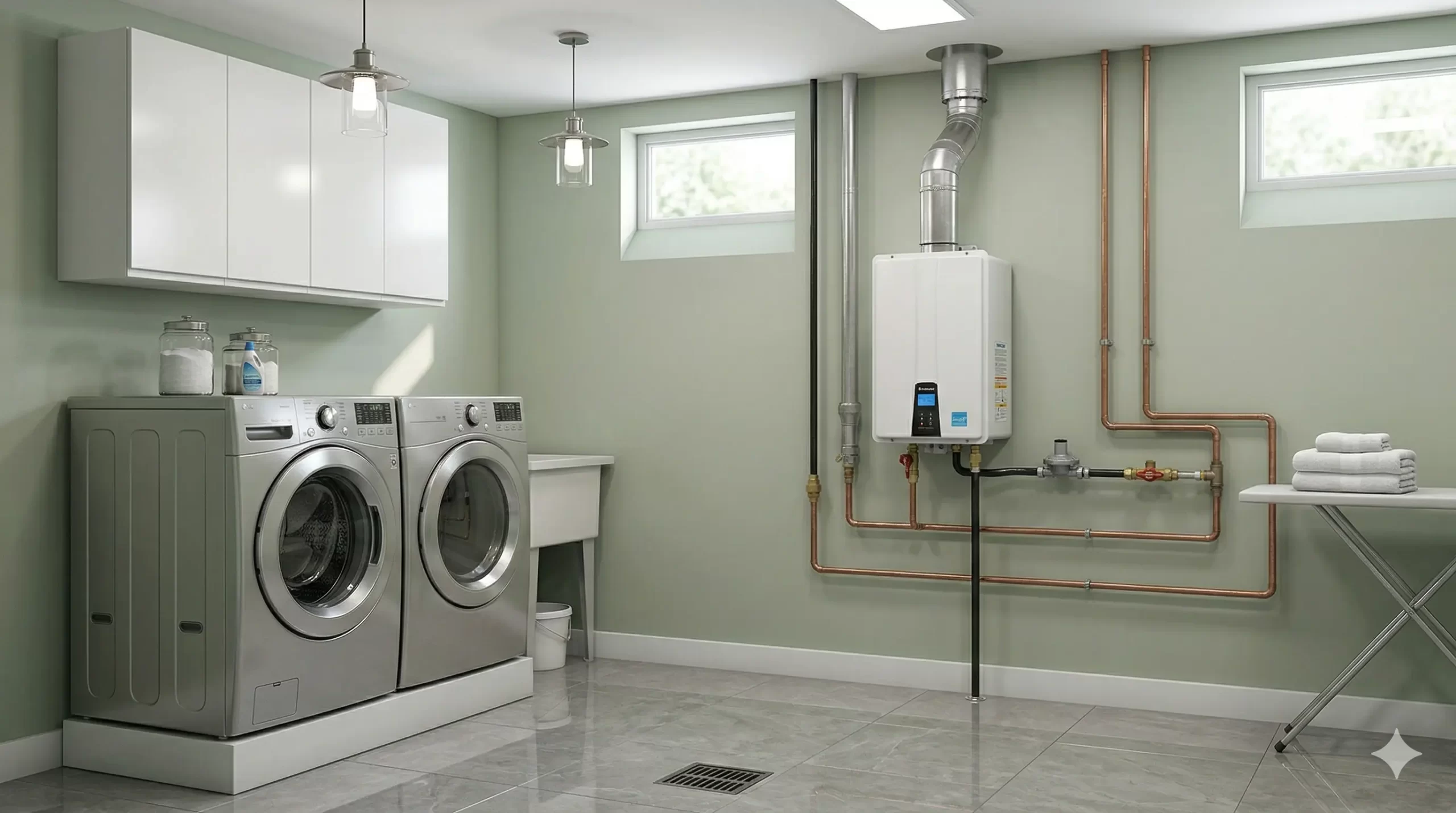
- Disconnect Gas and Electrical Lines: Using appropriate open-end wrenches, carefully disconnect the main burner supply tube, the pilot tube, and the thermocouple/thermopile lead from the bottom of the gas control valve. Note their positions for reassembly.
- Extract the Burner Assembly: Gently but firmly slide the entire burner assembly tray out of the combustion chamber. Be mindful of any attached igniter wires. Place it on a stable, non-flammable surface.
- Inspect and Clean Pilot Assembly: Visually inspect the thermopile probe for a white or black coating. Clean the probe with fine steel wool or emery cloth until it is shiny. Locate the pilot orifice and clean it by blowing compressed air through the pilot tube; never use a pin or wire, as this will damage the precision-drilled opening.
- Perform a Millivolt Output Test: Reconnect the thermopile lead to a multimeter set to DC millivolts. Temporarily reconnect the pilot tube to the GCV. Turn on the gas, light the pilot according to the manufacturer’s instructions, and measure the output. A healthy thermopile under a strong flame should read above 350mV. If the reading is low (e.g., under 300mV) with a clean, strong flame, the thermopile has failed and requires replacement.
- Replace Thermopile (If Necessary): If the millivolt test fails, procure the exact OEM replacement pilot/thermopile assembly for your Bradford White model. Install the new assembly onto the burner tray, ensuring it is oriented correctly so the flame will properly engulf the new probe.
- Reinstall Assembly and Reconnect Lines: Carefully slide the burner assembly back into the combustion chamber, ensuring it is fully seated. Reconnect the main burner tube, pilot tube, and new thermopile lead to the gas control valve. Use a minimal amount of approved pipe thread sealant on the threaded gas fittings only.
- Perform Gas Leak Test: Turn the main gas shutoff valve back on. Using a spray bottle with gas leak detection solution (or soapy water), spray every connection you disturbed. Look for bubbling, which indicates a leak that must be tightened and re-tested before proceeding.
- Relight and Verify Operation: Follow the lighting instructions on the water heater label. Once the main burner ignites, observe the status light. It should remain solid or blink once (normal operation), confirming the 2-blink fault has been cleared. Reinstall the inner and outer access doors securely.
Expert Verdict: Is It Worth Repairing?
For a Bradford White water heater exhibiting a 2-blink status light, a repair is almost always the most logical and financially sound decision, provided the unit is not past its expected service life. The thermopile is a consumable service part with a finite lifespan, and its failure does not indicate a systemic problem with the tank or gas control system. The cost of a professional repair, including diagnostics and the replacement part, typically represents less than 25% of the cost of a full water heater replacement and installation. Given that this repair restores the unit to its original operational safety and efficiency, the return on investment is extremely high, extending the life of an otherwise healthy appliance for several more years.
The decision matrix shifts only when the water heater is approaching or has exceeded its tank warranty period (often 6 to 10 years). If the unit is 12+ years old, and especially if this service call reveals other issues like a depleted anode rod or significant sediment in the tank, the repair cost should be weighed against the probability of future failures. In this scenario, repairing the weak pilot signal might only be a temporary fix before a more catastrophic (and costly) tank failure occurs. For any unit under 10 years old, however, addressing the 2-blink code is a targeted, effective, and highly recommended maintenance procedure.
Frequently Asked Questions (FAQ)
Q: Can a drafty room cause the 2-blink error on my Bradford White heater?
A: Yes, a strong draft can cause the pilot flame to deflect away from the thermopile probe. This lowers the temperature at the probe, which in turn reduces the millivolt output and can trigger the 2-blink ‘weak pilot signal’ fault code, even if the pilot assembly itself is perfectly clean.
Q: I cleaned my thermopile but the 2-blink code returned after a week. What’s next?
A: If a thorough cleaning provides only a temporary fix, it strongly indicates one of two issues: either the thermopile is failing and can no longer produce a stable voltage, or the pilot orifice is creating a fundamentally ‘dirty’ flame that is sooting the new surface rapidly. The next step is a professional millivolt output test to condemn the thermopile or diagnose the poor combustion.
Q: Is the 2-blink code related to the anode rod?
A: No, there is no direct relationship. The 2-blink code is exclusively part of the electronic gas control and combustion monitoring system. The anode rod is a component inside the tank that protects it from corrosion and has no interaction with the pilot flame or thermopile.
Q: Why does the status light blink 2 times instead of just shutting the heater down?
A: The 2-blink code is part of a ‘soft lockout’ diagnostic feature. It communicates the specific fault (weak pilot signal) to a technician rather than simply shutting down without information. This allows for precise and rapid troubleshooting, differentiating it from a ‘hard lockout’ which might indicate a more severe internal valve or sensor failure.