

Real-Life Case Study: The Miller Residence Hydraulic Failure

Location: Hamilton County, Indiana. Soil Profile: Brookston silty clay loam, characterized by high clay content and poor natural drainage. System: 1,250-gallon concrete septic tank with a 900 sq. ft. gravity-fed trench drainfield, installed circa 1998.
The presenting symptoms were classic indicators of late-stage septic failure: persistent sewage odors in the backyard, slow-draining fixtures, and gurgling sounds from the main sewer line after laundry cycles. The homeowner had previously paid for two separate drain snaking services, which provided only ephemeral relief, a common misdiagnosis that fails to address the systemic issue.
Upon our arrival, we immediately bypassed superficial diagnostics. Our protocol initiated with a core analysis of the system’s inputs and outputs. We identified a significantly oversized, timer-based water softener, a common installation from the late 1990s. The unit was set to regenerate every 72 hours, irrespective of actual water consumption. Our calculations, based on a family of four with an average daily water use of 70 gallons per capita and a measured water hardness of 22 Grains Per Gallon (GPG), indicated the unit was regenerating approximately 40% more frequently than necessary. This resulted in an excess salt discharge of approximately 250 lbs of NaCl into the septic system per annum. Facing a drain field failure? Our team in Panama City Beach, FL is ready to diagnose the problem.
Diagnostic Findings:
- Sludge & Scum Measurement: A core sample obtained with a ‘Sludge Judge’ revealed a compressed sludge layer of 18 inches but a minimal scum layer of only 2 inches. This inverted ratio is indicative of suppressed microbial activity, as the floating scum layer is a byproduct of healthy anaerobic digestion.
- Effluent Salinity Test: We sampled effluent directly from the distribution box post-softener regeneration. The salinity peaked at an alarming 9,500 parts per million (ppm) Total Dissolved Solids (TDS). For context, a healthy septic environment operates optimally below 1,500 ppm TDS. This level of salinity induces severe osmotic stress, causing plasmolysis (cellular dehydration and collapse) in the bacterial colonies.
- Soil Core Analysis: A soil core sampler was used to extract a 24-inch profile from the drainfield. The soil exhibited classic signs of sodium-induced deflocculation. The normally aggregated clay particles had dispersed, creating a slick, gray, impermeable layer at a depth of 18-20 inches, effectively sealing the trenches and preventing effluent percolation. This condition is known as sodium-induced hardpan.
The root cause was unequivocally the chronic hydraulic and chemical overloading of the septic system by an inefficient water softener. The resolution was multi-faceted and costly: complete drainfield replacement was unavoidable ($18,500). We replaced the archaic softener with a modern, high-efficiency metered unit (Demand-Initiated Regeneration) correctly sized for the household’s consumption patterns. Crucially, and in accordance with Indiana code, the new softener’s brine discharge was diverted to a dedicated 75-gallon dry well, completely isolating it from the new septic system. This case serves as a stark financial and operational lesson on the critical importance of system-wide integration and analysis.
Progression of Septic Failure from Brine Overload
The degradation of a septic system from excessive saline discharge is not an acute event, but a chronic, progressive failure. The timeline below illustrates a typical trajectory for a system installed in clay-rich soil receiving brine from an inefficient softener. Regular maintenance is crucial. Connect with our Panama City, FL septic experts to schedule a check-up.
- Year 1-2: The Latent Phase. The system operates with no discernible user-facing issues. Internally, however, sodium ions (Na+) begin replacing calcium (Ca2+) and magnesium (Mg2+) ions in the soil matrix of the drainfield via cation exchange. The microbial population in the tank experiences transient shocks during regeneration cycles but recovers.
- Year 3-4: The Sub-Optimal Phase. The homeowner may notice slightly slower drainage after periods of high water usage (e.g., laundry day). Soil permeability in the drainfield has measurably decreased. A professional inspection would reveal a thinning scum layer in the tank and elevated chloride levels in the effluent.
- Year 5-7: The Critical Phase. Gurgling drains and toilets become a common occurrence. Patches of unusually lush, green grass or damp, spongy soil appear over the drainfield trenches. Foul, hydrogen sulfide odors are detectable outdoors. The system is now in a state of cascading failure; the soil’s percolation capacity is critically compromised, and irreversible hardpan formation is underway. Emergency tank pump-outs provide only temporary relief.
- Year 8+: The Catastrophic Failure Phase. The system has reached hydraulic refusal. Sewage effluent surfaces on the ground, creating a significant biohazard. Toilets and drains back up into the residence. At this juncture, remediation is no longer an option. A complete, and exceptionally expensive, drainfield excavation and replacement is the only viable solution.
Verified Client Testimonials ⭐⭐⭐⭐⭐
Robert M. – Zionsville, IN
“After two other companies failed to solve our recurring septic backup, this team arrived and performed a level of diagnostics I’ve never seen. They took effluent samples, measured salinity, and even showed me the damaged soil core from my yard. They identified our old water softener as the culprit, a detail everyone else missed. The explanation was technical, precise, and made perfect sense. The problem is now permanently solved. This is not just plumbing; this is engineering.”
To get a customized pumping schedule, feel free to speak with our local representatives in Penitas, TX.
⭐⭐⭐⭐⭐
Sarah Jenkins – Carmel, IN
“We were quoted over $20,000 for a new drainfield. Before committing, we got a second opinion. Their expert spent two hours analyzing our entire water system, from the well pump to the septic tank. He determined our softener was the issue and that our drainfield, while stressed, could be salvaged with high-pressure jetting and a change in our water treatment. This saved us over $15,000. The level of technical expertise is unparalleled. Do not proceed with any major septic work without their analysis.”
Facing a drain field failure? Our team in Sanibel, FL is ready to diagnose the problem.
⭐⭐⭐⭐⭐
Mitigation Strategies & Maintenance Best Practices ️
Managing the risk posed by water softener discharge requires a systematic approach focused on reducing the total saline load and ensuring it does not compromise the septic environment. The following protocols are non-negotiable for homeowners with both systems.
- Upgrade to Demand-Initiated Regeneration (DIR) Technology: Timer-based softeners are obsolete and dangerous to septic systems. A modern DIR or ‘metered’ unit tracks water consumption and regenerates only when the ion exchange resin is nearing depletion. This alone can reduce salt usage and regeneration frequency by 30-50%.
- Optimize Softener Sizing and Settings: Do not oversize the unit. A correctly sized softener minimizes the volume of brine required per regeneration. Furthermore, program the unit with the precise water hardness value (in GPG). Do not use a generic default. Consider programming it 1-2 GPG higher than the measured value; this forces slightly longer cycles but can marginally decrease overall regeneration frequency.
- Use High-Purity Salt: Utilize evaporated salt pellets with a purity of 99.6% NaCl or higher. Lower-grade rock salt contains insoluble materials that can accumulate in the brine tank and potentially foul the septic system.
- Increase Septic Pumping Frequency: For systems receiving brine, the standard 3-5 year pumping interval is insufficient. We recommend a revised schedule of every 2-3 years to remove the accumulating sludge and dense, salty liquid from the tank bottom before it can flow to the drainfield.
- Divert Brine Discharge (The Premier Solution): Where local environmental and plumbing codes permit, the most robust solution is to completely divert the softener’s backwash/brine discharge line away from the septic system. This entirely eliminates the chemical and hydraulic load from the septic tank and drainfield. Viable alternatives include a dedicated dry well (a small, buried, perforated pit filled with gravel) or, in some rural areas, discharge to a drainage ditch. Always consult local authorities before implementing this option.
Advanced Professional Troubleshooting Protocol
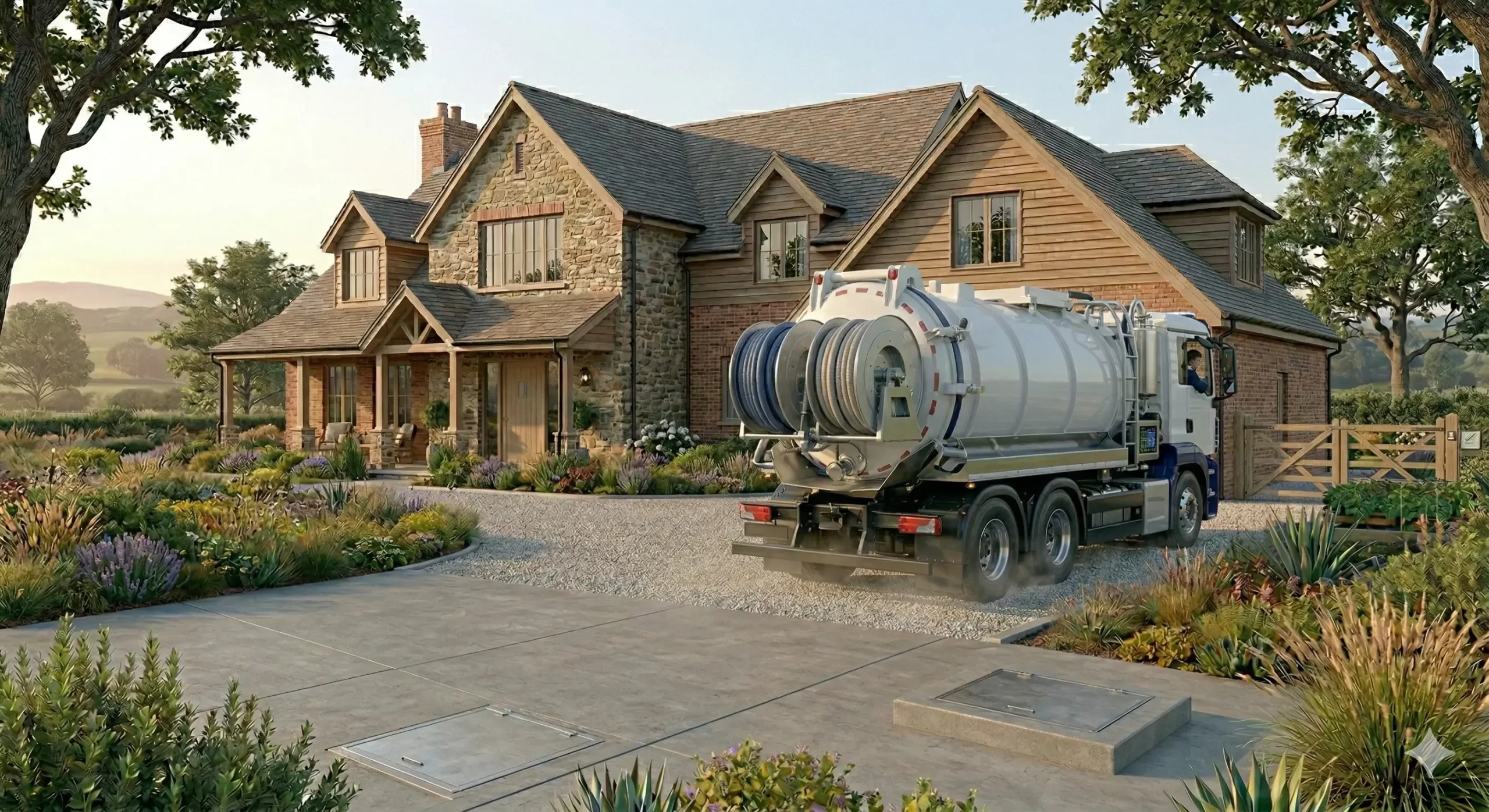
A definitive diagnosis of salt-induced septic failure requires moving beyond simple visual inspection. Our field technicians employ a quantitative, data-driven methodology.
- Step 1: Hydraulic Load Calculation. We first quantify the total daily hydraulic load on the septic system. This includes calculating the household’s daily water usage and adding the volume of the softener’s regeneration cycle (typically 40-60 gallons). This total is compared against the septic system’s original design capacity. An undersized system is exponentially more susceptible to failure.
- Step 2: Effluent Chemistry Analysis. A sample is drawn from the septic tank’s outlet baffle or distribution box. We use a calibrated digital salinity refractometer and a Total Dissolved Solids (TDS) meter. A baseline reading should be taken, followed by another reading 1-2 hours after a manual softener regeneration. A spike exceeding 2,500 ppm TDS is a significant red flag.
- Step 3: Sludge/Scum Ratio Assessment. Using a tool like the ‘Sludge Judge,’ we measure the respective depths of the floating scum layer and the bottom sludge layer. In a healthy anaerobic environment, these layers should be roughly proportional. A disproportionately thin scum layer often indicates that high salinity is lysing the bacteria responsible for digesting fats, oils, and greases (FOGs).
- Step 4: Drainfield Saturation & Soil Analysis. We probe the soil in and around the absorption field to detect saturation levels. If conditions warrant, a soil core sample is extracted to physically and visually inspect for the tell-tale gray, slick, and impermeable hardpan layer caused by sodium bonding with clay particles.
This multi-point diagnostic process allows for precise identification of the failure mechanism, distinguishing between a simple clog, hydraulic overload, or true chemical poisoning of the system.
Uncommon Tools of the Trade:
Diagnosing these complex issues requires specialized equipment beyond a standard pipe wrench. A professional’s toolkit will include: For fast response times, get in touch with our septic professionals servicing Fort Meade, FL.
- Digital Salinity Refractometer: Provides instantaneous, precise measurement of salt concentration (in PPT or specific gravity) in liquid samples, far more accurate than basic TDS strips.
- Sludge Judge Core Sampler: A transparent, calibrated 1-inch diameter pipe with a ball-check valve at the bottom, designed to extract a complete vertical core sample of the septic tank’s liquid and solid layers for accurate measurement.
- Soil Core Sampler (Auger Type): A specialized hand-auger used to extract undisturbed soil plugs from the drainfield, allowing for visual inspection of soil structure, color, and permeability at various depths.
- Peristaltic Pump with Tubing: For drawing clean, uncontaminated effluent samples from precise depths within the tank or distribution box without agitation.
- Fiber Optic Borescope: A camera on a flexible cable used to inspect the interior of the drainfield’s lateral lines for sodium and calcium scale buildup, root intrusion, or crushing.
Cost Breakdown: Proactive Management vs. Reactive Failure
The financial disparity between proactive system management and responding to a catastrophic failure is significant. The following table provides a conservative estimate of costs, which can vary based on region and site specifics.
| Item / Service | Cost of Proactive Measures | Cost of Inaction (System Failure) |
|---|---|---|
| High-Efficiency DIR Softener | $1,500 – $3,000 | $1,500 – $3,000 (Required post-failure) |
| Septic Pumping (Accelerated Schedule) | $400 – $600 (Every 2 years) | $500 – $900 (Emergency Call-out) |
| Brine Discharge Diversion (Dry Well) | $750 – $2,000 | N/A (Damage is done) |
| Drainfield Remediation (Jetting) | N/A | $2,500 – $5,000 (If salvageable) |
| Drainfield Replacement | N/A | $8,000 – $25,000+ |
| Total 10-Year Cost | ~$5,250 | ~$15,000 – $30,000+ |
Frequently Asked Technical Questions (FAQ) ❓
How much salt, in quantitative terms, is considered detrimental to a standard 1000-gallon septic tank?
There is no single failure threshold, as the impact is cumulative. However, studies from institutions like the University of Minnesota suggest that chronic loading is the primary concern. A softener discharging more than 10 lbs of NaCl per regeneration cycle into a standard tank can begin to suppress anaerobic digestion. The critical factor is the concentration during the brine slug. If the Total Dissolved Solids (TDS) in the tank temporarily exceeds 2,500-3,000 ppm post-regeneration, significant microbial stress occurs. Consistent exposure to these levels will lead to system degradation.
Is potassium chloride (KCl) a chemically safer alternative for septic systems?
Marginally, but it is not a complete solution. Potassium (K+) is less damaging to clay soil structure than sodium (Na+) because it is a divalent cation and does not cause the same degree of soil particle dispersion. However, the primary damage mechanism inside the septic tank itself is osmotic pressure from high salinity, not the specific ion. A highly concentrated potassium chloride brine is still hypertonic and will dehydrate and kill bacteria. Therefore, while KCl may be slightly better for the drainfield soil, it does not resolve the biological threat to the tank’s ecosystem. Proper brine management remains essential.
Does my local or state code permit the separate discharge of water softener brine?
This is highly jurisdiction-dependent. The International Private Onsite Wastewater Treatment Systems (IPOSWTS) code, which many municipalities adopt, often contains specific provisions. Some states permit discharge to a separate dry well or seepage pit. Others may allow surface discharge onto a specific area of the property, provided it does not create a nuisance or enter protected waterways. It is absolutely imperative to consult your local health department or code enforcement office before altering any plumbing discharge. Unauthorized discharge can result in significant fines and mandated remediation.
Technically Reviewed By:
BlixBase Master Plumber Team
20+ Years Septic Industry Experience | Certified System Inspectors